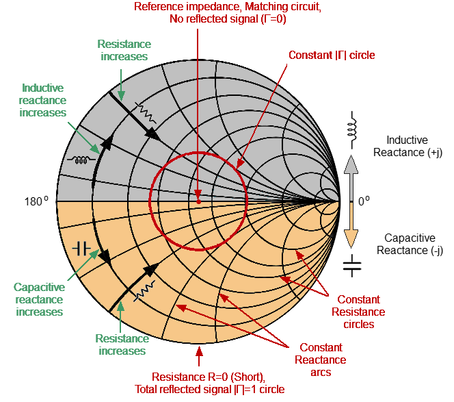
Smith Chart
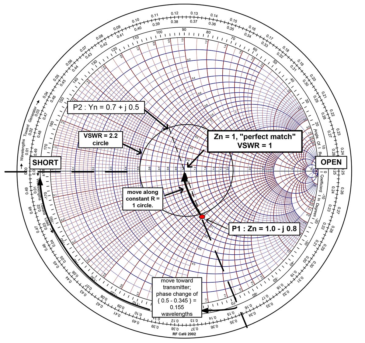
Smith Chart - Here sm ith chart is used to design an input/output matching network for a rf power transistor. This example refers to section 4.2 in motorola's application note an721. In the bottom of the window change gammas such that it moves to the. The next task is to cancel or tune out the reactive part, which is done by adding a series inductor and increasing its value until the center of the chart is reached. See the large signal amplifier. Finally we use an open circuit transmission line,. The collector capacitance, which is in parallel to the load, given by the data shee t is 40 pf. Av gain circle step size [degree]: Op gain circle step size [degree]: A) from the schematic window assign 0 ohm resistor to a series slot by dragging the resistor. This example refers to section 4.2 in motorola's application note an721. A) from the schematic window assign 0 ohm resistor to a series slot by dragging the resistor. The same is illustrated in the. Constant conductance circles can be drawn by using the show admittance function (admittance circles) in the display menu of chart window. Here sm ith chart is used to design an input/output matching network for a rf power transistor. See the large signal amplifier. Av gain circle step size [degree]: In the bottom of the window change gammas such that it moves to the. Op gain circle step size [degree]: The examples here mostly application oriented and does not get into theoretical d etails, it is however urged that the user should refer to standard text books for basic concepts on. These exercises uses basic resistance and reactance to illustrate their mapping on the chart. Here sm ith chart is used to design an input/output matching network for a rf power transistor. Constant conductance circles can be drawn by using the show admittance function (admittance circles) in the display menu of chart window. Av gain circle step size [degree]: The goal. The next task is to cancel or tune out the reactive part, which is done by adding a series inductor and increasing its value until the center of the chart is reached. These exercises uses basic resistance and reactance to illustrate their mapping on the chart. The goal is to navigate the blue dot on the smith chart to the. The same is illustrated in the. This example refers to section 4.2 in motorola's application note an721. Av gain circle step size [degree]: Op gain circle step size [degree]: The next task is to cancel or tune out the reactive part, which is done by adding a series inductor and increasing its value until the center of the chart is. A) from the schematic window assign 0 ohm resistor to a series slot by dragging the resistor. The same is illustrated in the. The next task is to cancel or tune out the reactive part, which is done by adding a series inductor and increasing its value until the center of the chart is reached. The examples here mostly application. Op gain circle step size [degree]: Constant conductance circles can be drawn by using the show admittance function (admittance circles) in the display menu of chart window. The next task is to cancel or tune out the reactive part, which is done by adding a series inductor and increasing its value until the center of the chart is reached. The. These exercises uses basic resistance and reactance to illustrate their mapping on the chart. Here sm ith chart is used to design an input/output matching network for a rf power transistor. Av gain circle step size [degree]: In the bottom of the window change gammas such that it moves to the. The same is illustrated in the. The same is illustrated in the. Op gain circle step size [degree]: The next task is to cancel or tune out the reactive part, which is done by adding a series inductor and increasing its value until the center of the chart is reached. In the bottom of the window change gammas such that it moves to the. The examples. The examples here mostly application oriented and does not get into theoretical d etails, it is however urged that the user should refer to standard text books for basic concepts on. A) from the schematic window assign 0 ohm resistor to a series slot by dragging the resistor. These exercises uses basic resistance and reactance to illustrate their mapping on. Finally we use an open circuit transmission line,. See the large signal amplifier. The next task is to cancel or tune out the reactive part, which is done by adding a series inductor and increasing its value until the center of the chart is reached. The goal is to navigate the blue dot on the smith chart to the circle. In the bottom of the window change gammas such that it moves to the. The next task is to cancel or tune out the reactive part, which is done by adding a series inductor and increasing its value until the center of the chart is reached. This example refers to section 4.2 in motorola's application note an721. A) from the. These exercises uses basic resistance and reactance to illustrate their mapping on the chart. This example refers to section 4.2 in motorola's application note an721. A) from the schematic window assign 0 ohm resistor to a series slot by dragging the resistor. Av gain circle step size [degree]: The examples here mostly application oriented and does not get into theoretical d etails, it is however urged that the user should refer to standard text books for basic concepts on. The goal is to navigate the blue dot on the smith chart to the circle going through the center and then use the last component to bring to the 50 ohm point. The next task is to cancel or tune out the reactive part, which is done by adding a series inductor and increasing its value until the center of the chart is reached. The same is illustrated in the. In the bottom of the window change gammas such that it moves to the. Finally we use an open circuit transmission line,. Constant conductance circles can be drawn by using the show admittance function (admittance circles) in the display menu of chart window. The collector capacitance, which is in parallel to the load, given by the data shee t is 40 pf.
The 25+ best Smith chart ideas on Pinterest
Smith Chart Format

The Smith Chart A Vital Graphical Tool DigiKey
Smith Chart course
Revisiting the Smith Chart AGC Systems
The Smith Chart Engineering Radio
Smith Chart Fundamentals Nuts & Volts Magazine
Smith Charts
Smith Chart Basics, Components, Types, Examples and Applications
Smith Charts
Op Gain Circle Step Size [Degree]:
Here Sm Ith Chart Is Used To Design An Input/Output Matching Network For A Rf Power Transistor.
See The Large Signal Amplifier.
Related Post: